|
Foctor Affecting Roller Chain Selection
For any application it is necessary to initially
establish certain essential information. This typically includes the
power to be transmitted, the drive shaft and driven shaft speeds (and
hence the reduction ratio), the duty (specified in terms of power
source, the severity of load and the design life), the shaft centre
distance, the operating environment (i.e. dampness, temperature, etc.)
and the likely level of maintenance (thus indicating lubrication types
that may be permissible).
Drive selection is at two level, at the transmission type level (i.e.
deciding whether to use chain drives, gears or pulleys) and at the
component level (i.e. choosing the chain pitch size, number of strands
etc.).
Transmission Type Selection
Many factors might influence why a chain drive will be selected for
power transmission in preference to gear or a belt drive. Typically, a
chain drive will be favoured when:
1. the centre distance between shafts is relatively large (making gears
impractical);
2. a synchronous drive is necessary (making wedge pulley belts
unsuitable);
3. a high operating efficiency and long life is required;
4. a high torque (or power) at slow speed is needed;
5. operating conditions are severe (pulleys are unsuitable in a wet, hot
or abrasive environment);
6. cost have to be minimal;
7. a number of shafts need to be driven in synchronism;
8. shaft alignment and centre distance may be of low precision.
Component Selection Level
The sequence taken in identifying suitable chain drives and then
choosing a preferred alternative is described in the flow diagram. A
summary of a worked example which follows the procedure taken in this
figure is given on a later page of this chapter. The following comments
will help to clarify details of the flow diagram and the example.
1. When establishing requirements, essential information will include
the drive and driven shaft speed, the power to be transmitted, the shaft
centre distance, the operating duty and permissible lubrication types.
2. To determine the number of teeth required for the drive and driven
sprockets it is first necessary to obtain the reduction ratio and this
is found from knowledge of the shaft speeds. Frequently, though, it is
not possible to achieve exactly the reduction required (since sprockets
are available only in a limited number of teeth sizes) and so some
tolerance on the driven shaft speed may have to be accepted. Also, the
greater the number of teeth in the pinion, the quieter and smoother the
transmission, and if low noise and very long life are desirable, a large
and thus more expensive chain assembly will be necessary.
3. Operating with a severe drive source and/or a driven load will
require a more substantial size of chain – and possibly large sprockets
also. To provide a reserve of capacity to compensate for more demanding
operational conditions, an appropriate Service Factor is used. This is
obtained from a table and applied to the actual power to be transmitted
thus producing an imaginary power which is then used for determining
suitable chain pitch sizes from a Power Rating Chart. To avoid the
necessity for having unique charts for each driving sprocket size and
multi-strand alternative, a term called the Selection Power is defined.
This quantity is calculated by simply applying factor to the actual
power to be transmitted so that a single Rating Chart may then be used.
4. Suitable chain pitch sizes, based on power considerations, will be
found from referring to the appropriate chain manufacturer’s
‘Transmission Rating Chart’ (found in a catalogue) and using the
calculated Selection Power and the drive shaft speed. Generally, the
large the chain pitch and the greater the number of strands, the greater
the power that can be transmitted.
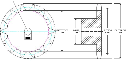
5. The chain pitch sizes must be checked for practical suitability,
sprocket diameter and minimum centre distances must be established so as
to ensure that alternatives are possible (see Figure 1).
6. Frequently the designer is faced with a number of viable alternatives
comprising different pitch sizes and multi-strand options and each will
have inherent advantages and disadvantages. For example, increasing the
pitch size results in larger chain links and sprocket diameters but with
consequent increased cost and reduced chain tension and speed
capability. In contrast, using multi strand chain results in an increase
of face width rather than diameter but it too is more expensive because
it necessitates having tandem chain and sprocket sets.
7. Full catalogue details of the chosen chain drive should be
summarized, together with connecting link type and tensioner (if
required) so that mating items can be designer. The required length may
be calculated by applying the appropriate equation. Usually it is more
practical to know the length in term of the number of link – rounding up
to the next integer number if part of a link is calculated, and using a
chain tensioner to take up any slack. The chain tension is important
when determining shaft forces and hence establishing shaft and bearing
suitability. Figure 1
Chain Power Rating
Many factors influence the amount of power which may safely be
transmitted by a chain assembly. Generally the larger the pitch size and
the larger the sprocket diameters the greater the power that can be
transmitted but the slower the speed that the chain can operate at.
This is because the larger the pin and bush sizes. The link is thus
stronger and the bushes have greater resistance to wear for a given
power and speed (hence torque and toot load). Conversely, for a given
reduction ratio, the larger the chain pitch the larger the sprockets and
hence peripheral speed. For a limiting operational chain velocity,
smaller pitch chain will operate at higher rotational speeds. In
addition to chain size, the recommended maximum operating power and
speed will depend upon factor such as the number of teeth in the
sprocket, the severity of use, the lubrication system and the number of
strands used.
Service Factor
The application suitability of a chain drive depends upon the type of
drive and also the class of load. Typically each is categorized into
three levels as follow:
Types of Drive
• Steady (e.g. ‘soft start’ electric motors)
• Medium Impulsive (e.g. single-cylinder i.c. engines)
• Highly impulsive (e.g. single-cylinder i.c. engines)
Types of load
• Class 1 for Smooth loads
• Class 2 for Moderate Shock loads
• Class 3 for Heavy Shock loads
Service Factor for the three classes of load severity are displayed
below based on a Driving Sprocket with 15 teeth.
Multi-Strand Factors
Using a multi-strand chain increases the power that can be transmitted
for a given pitch size but not fully in proportion with the number of
strands used. Typically, the following power rating factors are widely
used.
Selection (Design) Power
To minimize the number of charts needed in a catalogue it is necessary
to calculate the Selection Power ( Or Design Power as it is sometimes
referred). This obtained from :
Life Expectancy of Chains
A Chain’s life expectancy can be expressed as maximum percent of
elongation. When using up to 67-tooth sprockets, a normal life
expectancy is approximately 3% elongation. Thus, a chain should be
replaced when its length increases 0,36” per foot on the average, to
avoid sudden tension failure. When using sprockets with over 67 teeth,
life expectancy is reduced in relationship to foolowing formula:
Permissible chain elongation = 200 Where N is the number of teeth in the
larger sprocket.
N
Importance Lubrication
One of the most important, but often overlooked, factors affecting chain
life is proper lubrication. Besides minimizing metal-to-metal contact,
lubrication provides cooling and impact damping at high speeds. It also
reduces corrosion and carries away foreign matters, which is vital in
abrasive environmeters.
Lubricating method:
Normal Wear
Wear normally takes place in the pin bushing load-bearing areas. As they
wear, the chain gradually elongates. The rate of chain wear is greatly
affected by lubrication. When properly lubricated, load-bearing surfaces
of the pin and bushing will look shiny and smooth
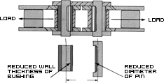
Bushing and Pin Wear Surfaces
Excessive Wear
If the load-bearing surface show discoloration (brown-red oxide),
lubrication is insufficient. Fretting corrosion has set in, and the
abrasive oxide produced will greatly increase the wear rate. Among other
causes of excessive wear are:
• Tight Chain, insufficient sag in the slack strand. Lessen idler
tension or distance between sprockets until slack is 2 to 3 % of the
sprocket center-to-center distance.
• Excessive Slack, chain whips and creates noise. Adjust idlers or
sprocket distance for proper slack.
• Worn or Misaligned Sprockets, can cause chain overloads and accelerate
the wear rate. Replace sprockets when teeth show excessive wear or are
hook-shaped.
Proper sprocket size is also important to minimize the wear rate. Use
sprockets with a minimum of fifteen teeth for smoothest operation and
loogest life. The fewer teeth there are in a sprocket, the greater the
wear rate because of high angle of articulation.
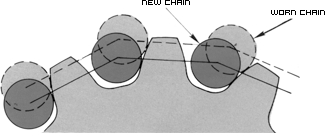
Changes in Tooth Engagement Caused by Chain Wear
Galling (Abnormal Wear)
Galling, or the tearing away of metal particles from the load-bearing
surface, occurs as a result of inadequate lubrication or excessive
operating speed. The mating surface of the pins and bushings actually
weld together, then break away as the joints flex over the sprockets.
Once started, galling accelerates rapidly and is highly destructive.
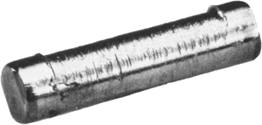
Pin Galling
Galling can occur at high speed if lubrication is inadequate or
misdirected. Check lubrication system to be sure that:
a. Proper type of lubricant is being used.
b. Lubricant flow is not obstructed.
c. Lubricant is penetrating chain joints
Tension Failure
This type of failure occurs when the ultimate tensile strength of a
chain is exceeded (when the chain is subjected to a one-time load
greater than it can withstand). Normally, tension failure can be
identified by fracture side plates showing a definite yield (a
taffy-pull type stretch) in the metal itself.
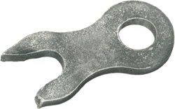
Side Plate Fracture Due to Tension Failure
Pin fracture, either near the center of the pin or a pin shear failure
between the side plates, can also be a result of tension failure. When a
chain breaks because of shocks or overloads, all of its components are
affected, even though the unbroken parts may appear sound. To avoid
repetitive failure, the entire chain should be replaced.
Tension failure can result from any condition which creates improper
engagement between link and sprockets. Characterized by the chain riding
up on the sprocket teeth. Such conditions include several already
mentioned: excessive chain elongation, excessive slack, sprocket
misalignment and worn sprockets.
In addition, dirt and foreign matter buildup in the sprocket tooth
pockets will prevent proper seating of the chain, creating an overload
condition between link and tooth. Sprocket should be checked
periodically, and any foreign material accumulation removed.
Another variation of tension failure is cracked bushings. In
applications contaminated by dirt or grit, abrasive material may
penetrate the links. When it reaches the inside and outside bushing
surfaces, this material literally grinds into the bushings during
articulation, reducing their wall thickness and lowering chain tensile
strength. Eventually the bushings crack under load.
Fatigue Failure
Fatigue failure are a result of repeated cyclic loading beyond the
chain’s endurance limit, or rated capacity. Extend of the overload and
frequency of its occurrence are factors which determine when fatigue
will occur. The overloading can be continuous or intermittent (impulse
load).
Continuous overloading may be causes by worn teeth or pocked buildup,
imposing overloads with each cycle. Impulse overloads can be from motor
overload torque, dynamic overloading due to sudden stops, or impact
loading on equipment.
Generally, a fatigue crack stars at the point of highest stress, which
is the aperture of the pin or bushing plate. Repeated cyclic stresses
cause the crack to extend approximately perpendicular to the pitch line
of the chain until plate breaks. Unlike a pure tension failure, there is
no noticeable yielding (stretch) of material.
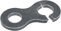
Fatigue Failure
When fatigue failure occurs, the application should be examined for
continuous or impulse overloading conditions. Determine the cause of the
overload and eliminate it if possible. (Be sure to check sprockets for
worn teeth or pocket buildup). If the cause cannot be eliminated,
determine the extent of the overload and increase chain size (capacity)
to accommodate the operating conditions.
Bushing fatigue is another type of fatigue failure. Such fatigue
manifests it self as circumferential crack near the bushing link plate
or longitudinally along the length of the bushing. Both types of cracks
may also appear in the same bushing. If bushing cracks are evident, do
not try to repair the chain. Determine and correct the cause of the
failure, then replace the entire chain.
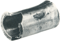
Bushing Fatigue
Stress Corrosion and Hydrogen Embrittlement
These closely related failures are similar in appearance and nature.
They appear as crack which initiate at the point of highest stress and
tend to extend in an arc-like path parallel
To the rolling grain of the material. Often, more than one crack will
appear on a side plate.
This type of failure can be caused by operating in an acidic or caustic
medium or atmosphere. Carbon steel and certain grades of stainless steel
are subject to stress corrosion cracking when exposed to a corrosive
environment. Also, exposure of carbon steel chain to moisture can lead
to rusting and stress corrosion cracking.
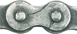
Stress Corrosion
The reactions of many chemical agents with metals liberate hydrogen,
which attacks and weakens the metal grain structure.
If stress corrosion failure occurs, check the installation to see if the
chain is exposed to chemicals, gases, moisture or other possible causes.
If the chain has been cleaned with a detergent solution, the detergent
could be at fault. For cleaning purposes, use only detergent-free
fluids. Never use acids, such as in acid bath degreasing. If the
detrimental conditions cannot be eliminated, consult REXTON for
alternative solutions. |


